
When selecting an industrial dust collection system, flow rate, dust characteristics, temperature, humidity, filter area, differential pressure, fan and emission target must all be evaluated together.
Why Isn't Industrial Dust Collection System Selection Just About "How Many m³/h?"
An industrial dust collection system is not selected based solely on the question “how many m³/h of air will be drawn?” For the right system selection, where the dust is generated, how it will be captured, the required suction flow, particle size, dust load, temperature, humidity, target emission level, filter area, differential pressure, fan operating point, hopper discharge arrangement, and process variability must all be evaluated together.
For this reason, two facilities with the same 50,000 m³/h flow rate may require completely different solutions. A compact cartridge filter may be sufficient for one, while the other may require a low-filtration-velocity pulse-jet baghouse, a pre-separator cyclone, specialized filter media, and a wear-resistant duct system.
Hantech's core decision statement
The right question is not "which filter should I buy?" but with what system behavior should I control the dust from its source all the way to the stack?
Don't Start Dust Collection System Selection with the Filter
The most common wrong approach seen in the field is this: “There's a 30,000 m³/h fan on site — let's pick a filter to match it.” This designs the system backwards. The existing fan's nameplate doesn't prove the process actually needs that flow rate; the fan may have been sized incorrectly, may be throttled by a damper, may be running against excessive system resistance, or may be pulling in leakage air.
In Hantech's approach, the existing equipment nameplate is only a data point, not the design itself. Process requirements and capture conditions are defined first, and only then are the filter and fan selected.
Know Your Dust First: Particle Size, Humidity, Chemistry, and Explosion Risk
The first real engineering step in filter selection is dust characterization. Coarse, heavy particles do not behave the same way as very fine particles. Abrasive dust can cause rapid wear in duct elbows, cyclones, fan impellers, and filter inlet plates. Hygroscopic or sticky dust, on the other hand, can rapidly raise dP once it absorbs moisture.
| Dust property | How does it change the design? | Hantech check |
|---|---|---|
| Size of particle | Affects the cyclone, cartridge, baghouse filter, and media decision | A micron distribution or on-site sample is requested |
| Corrosivity | Duct velocity, elbows, fan, and inlet protection change | Wear zones and material drop points are examined |
| No / dew point | Creates a risk of cake sticking and media blinding | Temperature, insulation, and start-stop behavior are assessed |
| Chemical environment | Changes the choice among PES/PPS/aramid/P84/PTFE | SOx, NOx, HCl, HF, O₂, and moisture are evaluated together |
| Flammability / explosibility | The safety concept changes entirely | ATEX/NFPA/project standard and risk analysis are required |
If combustible dust is a possibility, this is not an accessory item at the end of the filter selection process. The dust collector housing, ductwork, hopper, fan, and discharge equipment must all be considered together with respect to potential pressure rise, spark propagation, and flame spread. This is why venting, isolation, suppression, spark detection, antistatic media, and the grounding concept should be evaluated at the start of the design.
Hantech Engineering Note
"Let's pick the filter first and add the explosion vent later" is not the right approach. If there is an explosion risk, the safety concept must be one of the initial inputs to the system design.
Where Is the Dust Generated? Don't Oversize the Fan Before Solving Hood and Capture Design
In many poorly performing systems, the real problem is not the filter — it is a poorly designed hood. What matters is the direction dust moves at the belt transfer point, silo fill spout, crusher discharge, or hopper top, along with material drop height, ambient air movement, conveyor speed, enclosure geometry, and open surface area.
If the hood is positioned too far from the dust source, using a larger fan can increase energy consumption without improving capture performance to the same degree. The correct approach in local extraction is to capture the dust cloud as close to the source as possible, with the lowest unnecessary air volume, before it spreads into the production area. This is why hood distance, opening area, enclosure, and process air movement are checked before fan capacity.
How Is the Required Flow Rate Determined?
The basic relationship is Q = A × v; however, this formula alone does not determine the “required system flow rate.” The air volume needed for a hood depends on opening geometry, the dust's momentum-driven movement, the required capture conditions, and the enclosure level. The duct cross-section is then sized to convey the calculated airflow at the appropriate velocity.
This approach can be wrong: "We have a Ø500 duct, let's run it at 20 m/s, and select the filter based on whatever flow results." The existing duct geometry should not dictate the process requirement. The duct must instead be sized to carry the flow rate the process needs without allowing dust to settle.
Too Much Airflow Can Also Be a Poor Design
In dust collection, “more air is always better” is not true. Unnecessarily high flow rate can mean a larger filter, a larger fan, higher electricity consumption, larger ductwork, higher abrasion, unnecessary air being pulled from the process, and energy loss in hot processes.
If excessive air is drawn from hot processes in particular, the cost is not limited to the fan motor's kW rating — process energy can be lost as well. The design goal is not maximum flow, but the optimum flow that achieves the required capture.
Cyclone, Baghouse Filter, or Cartridge Filter?
There is no single “best dust collection technology.” The right choice depends on process conditions.
| System | An area where it is generally strong | Key point of attention |
|---|---|---|
| cyclone | Coarse/heavy particles, high load, pre-separation | May not be sufficient on its own for final emission control with fine particles |
| Pulse-jet baghouse filter | High dust load, continuous industrial processes | Media, A/C ratio, and cleaning design are critical |
| Cartridge filter | Compact design, suited to fine/dry dust applications | May not be suitable for heavy loads, fibrous/sticky dust, or high temperature |
| Wet scrubber | Applications where wet collection suits the process | Wastewater, sludge, corrosion, and pressure drop are evaluated together |
| Multistage system | Heavy + fine dust combination | CAPEX increases; downstream equipment load can be reduced |
Performance in baghouse filters cannot be explained by housing size alone. Particle load, how the dust settles onto the media, filter-cake behavior, cleaning method, pulse energy, and media selection together determine the outcome. This is why the same baghouse type can show different dP, emission, and bag-life behavior under different dust and gas conditions.
When Do We Not Use a Cyclone on Its Own?
A cyclone is very useful thanks to its lack of moving parts, simple design, and tolerance for high dust loads. But if there's a fine-particle emission target, relying on the cyclone alone may not be the right approach. For processes with very heavy dust loading, the right solution is sometimes a cyclone → baghouse combination.
Hantech Engineering Note
Placing a cyclone ahead of every baghouse isn't right either. A cyclone adds extra pressure drop, investment cost, and space requirements. The right question isn't “is a cyclone good” — it's does the cyclone meaningfully reduce the downstream load in this process?
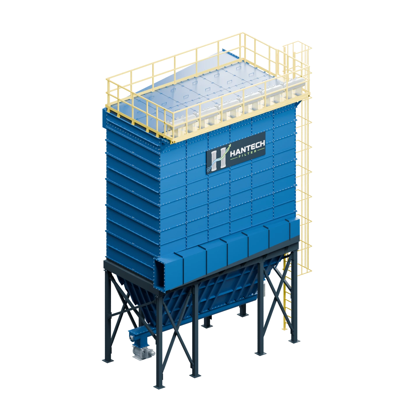
When Does a Baghouse Make Sense?
Baghouse filters are widely used in heavy processes such as cement, lime, minerals, metallurgy, foundry, power generation, and bulk material handling. But simply saying “let's use a baghouse” is not a design.
| Order | - why it is critical |
|---|---|
| Filter bag diameter, length, and quantity | Determines total filter area and housing geometry |
| Media and surface finish | Selected based on temperature, humidity, chemistry, and emission target |
| Cleaning system | Affects dP stability and filter bag life |
| Pulse valve / blow pipe geometry | Determines how cleaning energy is distributed across the filter bag |
| Hopper and inlet design | Affects dust distribution, re-entrainment, and abrasion |
| quiescent point | Shows whether the actual flow rate is being achieved for the selected filter area |
How Is Filtration Velocity Calculated?
One of the fundamental calculations in baghouse selection is total filter area. The approximate active surface area of a cylindrical filter bag can be calculated as A = π × D × L, and the total area as At = π × D × L × N. Filtration velocity is read as Vf = Q / At.
Worked example: 45,000 m³/h system
- Flow Rate
- 45,000 m³/h
- Bag
- 1,000 pcs, Ø150 mm, 3,000 mm
- Area of a bag
- π × 0.150 × 3 = 1.414 m²
- Total Area
- 1.000 × 1,414 = 1.414 m²
- filtration rate)
- 45,000 / 1,414 = 31.8 m³/m²·h = 0.53 m/min
Is 0.53 m/min good? This question should not be answered by looking at the number alone. The same filtration velocity may run stably with dry, free-flowing dust, but can cause high ΔP and cleaning problems with sticky or moist dust. The A/C ratio is a design parameter, not a quality indicator on its own.
A Lower Filtration Velocity Is Not Always Better
"The lower the filtration velocity, the better" is not always a valid generalization. An excessively low filtration velocity can mean a larger housing, higher CAPEX, more filter bags, more cages, more pulse valves, and more maintenance points.
An excessively high filtration velocity, on the other hand, can increase the risk of high ΔP, cleaning difficulty, short filter bag life, and emission problems. The right design is the optimum filtration velocity the process actually requires.
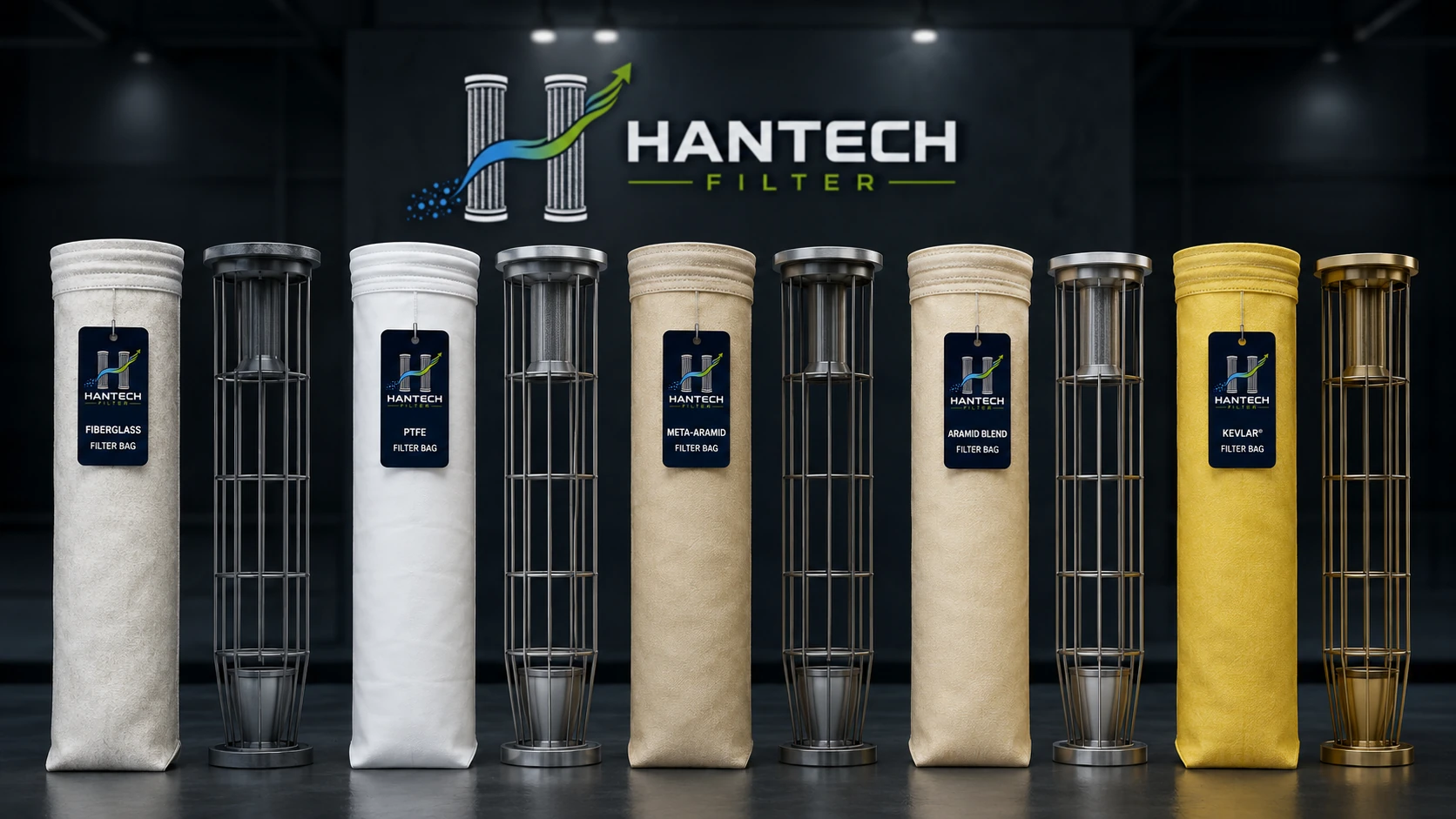
How Is Filter Media Selected? We Don't Automatically Choose PTFE
Looking only at the continuous temperature limit when selecting media is a serious mistake. Continuous operating and short-term upset temperatures, moisture/dew point, acid/alkaline character, oxidation, hydrolysis risk, particle characteristics, the cleaning system, and the target emission level must all be evaluated together.
Differential Pressure Is at the Center of the Design
One of the most valuable indicators in baghouse operation is differential pressure. ΔP tells you about the dust cake, media condition, filtration velocity, cleaning performance, moisture, gas distribution, and process load. However, the trend is more valuable than a single instantaneous ΔP reading.
| Symptom | Possible cause | First Check |
|---|---|---|
| ΔP is rising slowly | Media blinding, inadequate cleaning, moisture, or increased load | dP trend, pulse system, process load |
| ΔP drops suddenly | Filter bag tear, bypass, air leakage, or drop in process flow rate | Emissions, leak test, cell plate |
| ΔP high + weak suction | High A/C, blinded media, hopper, or cleaning problem | Filter and cleaning system |
| ΔP normal + weak suction | Fan, duct, damper, hood, or false air | Field flow rate and static pressure measurement |
Don't Increase Pulse Duration Just Because ΔP Is High
The classic field reflex is “the filter isn't pulling, so increase the pulse duration.” That isn't always correct. Applying more aggressive pulsing to media that's blinded or has absorbed moisture may not solve the problem — it can instead increase mechanical stress on the bag.
Fan Selection Is Not Made Separately from Filter Selection
The fan's job in a dust collection system is not just to “pull air.” The fan must deliver the required flow rate against the system's total resistance curve. Approximate system pressure loss is considered along this chain:
System pressure chain
ΔPsystem = ΔPhood + ΔPduct + ΔPcyclone + ΔPfilter + ΔPstack + other losses
Solved fan sample
- Flow Rate
- 45,000 m³/h = 12.5 m³/s
- Hood + entrances
- 250 Pa
- Ducting
- 900 Pa
- Filter
- 1,500 Pa
- Chimney + accessory
- 350 Pa
- Total
- 3,000 Pa
- Yield assumption
- η = 0,72
Spindle Power - 12.5 × 3,000 / 0.72 = 52.1 kW
This calculation alone is not enough to determine a motor rating. The fan curve, maximum power point, operating range, motor efficiency, transmission, density/temperature corrections, and operating scenarios must also be evaluated. A decision should never be made simply as "we calculated 52 kW, so let's fit a 55 kW motor."
Fan Curve and System Curve Must Be Evaluated Together
The actual operating point is where the fan curve intersects the system curve. In a system that runs at 45,000 m³/h with a clean filter, as the filter ΔP rises over time the system curve shifts upward. The same fan may then operate at, for example, 39,000 m³/h.
In such a case, saying "the fan is too small, let's get a bigger one" can be a wrong diagnosis. The real problem may be the filter's rising resistance, duct blockage, damper position, or false air. For details, see the fan flow rate and static pressure calculation guide.
When Would I Not Choose a Bigger Fan?
In some cases, a larger fan only masks the real problem. The system bottleneck must be found first.
Why Is False Air Critical?
In filter systems operating under negative pressure, leak air entering from the surrounding environment consumes fan capacity. For example, a fan may be drawing 200,000 m³/h; but if 40,000 m³/h of that is leak air, only 160,000 m³/h is effectively drawn from the process.
If the operator looks only at fan flow rate, they may conclude "our flow is sufficient" — yet suction on the process side is weak. In an actual retrofit study, the O₂ profile, temperature variation, static pressure, flow rate, and damper position are evaluated together to locate leak points.
Why Do Filter Inlet Design and Hopper Discharge Matter?
Two baghouses with the same number of bags and the same filter media can perform very differently. The cause is often gas distribution. With a poorly designed inlet, some bags see high local velocity while other areas remain underloaded; this can produce local wear, shortened bag life, uneven cleaning, and high ΔP.
Even a perfectly performing filter media can't save the system if the hopper doesn't discharge. Hopper angle, bridging, rotary valve capacity, screw conveyor capacity, airlock sealing, level control, and the risk of dust re-entrainment must all be checked.
Minimum Data Required for New System Design
| Group | Required data |
|---|---|
| Process | Process type, operating hours, normal/maximum capacity, simultaneous extraction points |
| Accelerate | Flow rate, temperature, min/max temperature, moisture, and gas composition if needed |
| Dust | Type, bulk density, particle size distribution, dust loading, abrasiveness, stickiness, flammability/explosibility risk |
| Emission | Current value, target value, and regulatory/process limit |
| Filter | Existing filter area, filter bag count, diameter, length, media, and ΔP trend |
| Fan | Model, flow rate, pressure, motor kW, motor current, RPM, and damper/VFD status |
You can share this data through the quote form. When needed, Hantech verifies the actual flow rate and pressure operating point with a site performance measurement.
How Is a Site Measurement Performed on an Existing Dust Collection System?
For retrofit or troubleshooting work, the system's actual operating point should be measured rather than relying on catalog data.
This makes it possible to confirm or rule out the assessment that "the fan is undersized." Sometimes the fan is not undersized — system resistance has increased. Sometimes the filter is not undersized — the hood is poorly designed. And sometimes flow is present, but leakage air has consumed the process suction.
Quick Fault Diagnosis Matrix
| Symptom | First area to look at |
|---|---|
| Weak suction + high filter ΔP | Filter / cleaning / high A/C ratio |
| Weak suction + normal filter ΔP | Fan / duct / damper / hood |
| ΔP is continuously rising | Blinded media / moisture / cleaning |
| ΔP suddenly dropped + emission increased | Filter bag leakage / bypass |
| Fan current changed | Fan operating point + impeller characteristics |
| Some bags wear out prematurely | Inlet distribution / local velocity |
| Hopper filling up | Rotary valve / screw conveyor / bridging |
| Pressure not recovering after the pulse | Compressed-air capacity |
| Flow is present but process suction is low | False air / hood design |
| High energy consumption but insufficient suction | System resistance / wrong operating point |
This table is a starting point for diagnosis; it is not a definitive failure determination on its own.
The 10 Most Common Selection Mistakes
New System or Retrofit?
If an existing dust collection system is performing poorly, a complete overhaul is not always necessary. The bottleneck should be identified first.
| Measurement / status | priority decision, 85 |
|---|---|
| Filter area is sufficient but the fan is inadequate | A fan retrofit can be considered |
| Fan is adequate but filter ΔP is too high | Filter / cleaning / media problem must be resolved |
| Both are adequate, but extraction is poor | The hood and duct system should be examined |
| Filter housing is good but emissions are high | Media, sealing, filter cage, cell plate, and bypass points are examined |
| Filter area insufficient after a process capacity increase | An extension or a new filtration module can be considered |
The goal of a retrofit is not to sell new equipment, but to remove the actual bottleneck.
How Does Hantech Approach a System?
Hantech reads actual flow rate, static pressure, filter ΔP, temperature, process values, motor/RPM, and, where needed, O₂ measurements together with the required process flow rate, filter area, A/C ratio, duct losses, total system resistance, and fan operating-point calculations.
For this reason, our conclusion on some projects is "a new filter is not needed" or "instead of upsizing the fan, the leakage and resistance problems in the existing system should be fixed." The goal is to determine the system's actual requirement before the initial investment cost.
Industrial Dust Collection System Selection Summary
The correct engineering approach is simple: measure → calculate → identify the root cause → then select equipment. Hantech Filter evaluates baghouse filter systems, cyclone pre-separators, industrial fans, filter bags, and rotary airlock equipment as a single system behavior.
Frequently Asked Questions
How is dust collection system capacity calculated?
System capacity isn't determined by the existing duct diameter alone. First, the required capture conditions and flow rates at the extraction points are established; total flow rate is then calculated taking into account simultaneously operating points, duct losses, and the process scenario.
Which is better: a bag filter or a cartridge filter?
In general, neither is better than the other. The selection should be made based on dust load, temperature, moisture, particle structure, area, maintenance, and process conditions.
Can it be used in place of a cyclone separator?
A cyclone can be sufficient in some coarse-particle applications. For fine-particle and low-emission targets, however, it is usually considered a pre-separator rather than an alternative to the final filter.
How is a filter fan selected?
First, the required flow rate and the pressure loss of the entire system are calculated. Then the operating point where the fan curve intersects the system curve is evaluated. Selection should not be made on motor power or nominal fan flow rate alone.
Why does filter differential pressure rise?
There can be many causes — high filtration velocity, insufficient cleaning, blinded media, moisture/condensation, an increase in process load, or a hopper problem. ΔP alone is not a diagnosis; it must be evaluated together with trends.
Does a Bigger Fan Solve the Suction Problem?
Not always. If there is a hood geometry, duct resistance, false-air, filter ΔP, or process problem, a larger fan may only increase energy consumption.
How is the number of filter bags calculated?
Once the required filter area is determined, the active area of a single bag is calculated based on the diameter and length of the bag to be used. The bag count can be determined by dividing the total required area by this value; the actual design should be made together with the cleaning system, compartment structure, and process conditions.
Conclusion: Choose a System, Not Just a Filter
The most costly mistake in an industrial dust collection system is often not choosing the wrong brand, but misdiagnosing the problem. A draft/suction problem may be blamed on the fan, leading to an unnecessary fan upsize. High ΔP may be blamed on the media, leading to replacing all the bags. An emission problem may be attributed to bag quality when the real cause is a leaking cell plate seal. Insufficient flow may be attributed to fan capacity when the system actually has significant false air.
When selecting a dust collection system, Hantech Filter does not treat the filter, fan or filter bag as independent products, but evaluates them as a single air and particulate handling system from hood to stack. The goal is not just to install new equipment, but to achieve the required emission performance with the right balance of energy consumption, differential pressure, maintenance needs and equipment life.