

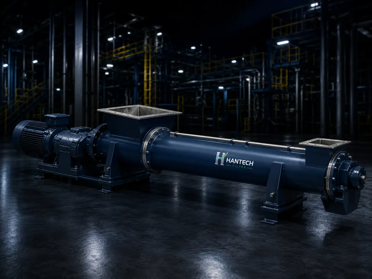
Work through screw capacity in m³/h and t/h. Interpret fill, bulk density, inclination and feeder duty correctly, and separate capacity from motor sizing.
Preparation method: manufacturer application information, process risks and engineering examples with explicit assumptions were assessed together. Numerical examples are not field measurements.
What determines screw conveyor capacity?
Screw conveyor sizing starts by converting required mass flow into volumetric flow using actual bulk density. Outside diameter, centre-pipe diameter, pitch, speed and assumed fill provide a preliminary geometric check. The result is neither guaranteed throughput nor motor power. Inclination, material slip, adhesion, abrasion, inlet feeding and discharge restrictions can alter performance. Applying a controlled-feed horizontal conveyor calculation directly to a flood-loaded screw feeder beneath a hopper is a major selection error.
The example below is a preliminary assessment of a horizontal, constant-pitch screw conveying dry bulk solids. Fill and density are explicit assumptions, not universal selection factors. The purpose is to expose the conditions behind a quoted tonnage and define the verification required from the manufacturer.
Working principle: distinguish conveyor from feeder
A rotating screw advances material along its pitch. A conveyor generally receives a flow controlled by upstream equipment; a screw feeder extracts material from a hopper and controls the flow itself. Inlet loading, starting torque and hopper head differ for a feeder. Increasing speed alone does not fix a bridging hopper, restricted outlet or worn flight; it may only worsen power demand and wear.
Selection data and unit table
| Variable | Example | Control |
|---|---|---|
| Outside diameter D / pipe diameter d | 0,300 / 0,089 m | Do not confuse with casing diameter |
| Pitch p | 0,300 m | Special flight geometry needs separate treatment |
| Speed n | 60 rpm | Screw speed, not motor speed |
| Fill φ | 0,30 | Assumption for this example |
| Bulk density ρ | 800 kg/m³ | Not particle density |
Worked calculation: from m³/h to t/h
A preliminary geometric model is Qv = 60 × [π × (D² − d²) / 4] × p × n × φ. With dimensions in metres and n in rpm, Qv is in m³/h. Example cross-section = π × (0.300² − 0.089²) / 4 = 0.06446 m². Qv = 60 × 0.06446 × 0.300 × 60 × 0.30 = 20.89 m³/h. Mass capacity Qm = Qv × ρ / 1000 = 20.89 × 800 / 1000 = 16.71 t/h, with rounding applied at the end.
The expression is a simplified volume model assuming material advances one pitch per revolution. It does not resolve slip, flight thickness, hanger bearings or inlet/outlet effects. Thus 16.71 t/h is not a test result. Final capacity requires manufacturer material factors, permitted speed and, when needed, product testing. Apparent preliminary capacity above a 15 t/h requirement does not prove that uncertain effects are safely covered.
What happens when bulk density changes?
| Bulk density | Approximate mass flow at 20.89 m³/h | Volume required for 15 t/h |
|---|---|---|
| 600 kg/m³ | 12.53 t/h | 25.00 m³/h |
| 800 kg/m³ | 16.71 t/h | 18.75 m³/h |
| 1000 kg/m³ | 20.89 t/h | 15.00 m³/h |
For the same 15 t/h target, reducing bulk density from 800 to 600 kg/m³ increases required volume by one third. Hantech asks for the range covering aerated and compacted conditions, not just an average. Low density can challenge volumetric capacity, while high density requires separate mechanical-load and torque checks. Changing moisture must not be assumed to leave flowability unchanged.
Process applications and when this model is unsuitable
Filter-hopper dust, cement transfer and dry mineral feeding have different abrasion and loading conditions. We would not turn this simple horizontal model into a performance guarantee for inclined equipment, ribbon or cut flights, multiple inlets or hopper feeders. Vertical conveying needs a separate selection method. Thermal expansion, hygienic/chemical compatibility and combustible-dust assessment also require duty-specific treatment.
Motor power cannot be derived from this volume calculation alone. It requires length, bearings, friction, material resistance, inclination, loaded starting and drive efficiency. A correct throughput calculation can still accompany an undersized motor. For frequently cycled hopper discharge, check loaded-start torque alongside the downstream rotary valve capacity.
Field diagnosis and quotation inputs
In an illustrative case, the screw rotates but weighed throughput falls. Speed is not the only check: examine hopper flow, actual bulk density, inlet loading, outlet accumulation and flight wear. Do not open covers without safe shutdown and energy isolation. Provide material samples/properties, minimum and maximum density, moisture, particle size, hourly and peak flow, centreline length, inclination, inlet/outlet dimensions, duty cycle and loaded-start requirements for a quotation.
- Screw conveyor products and layouts
- Rotary airlock selection at hopper discharge
- Request a screw conveyor quote with your material data
Frequently Asked Questions
Does screw capacity increase linearly with speed?
In the simple geometric model, yes; actual performance is constrained by slip, feeding and permitted speed.
Is fill always 30%?
No. It is only an illustrative assumption here; flowability, abrasion and manufacturer selection determine it.
Can particle density replace bulk density?
No. Conveyed volume includes spaces between particles; use bulk density at the relevant operating condition.
Can motor kW be obtained from capacity alone?
No. A separate power and torque assessment must include length, resistances, inclination and loaded starting.