

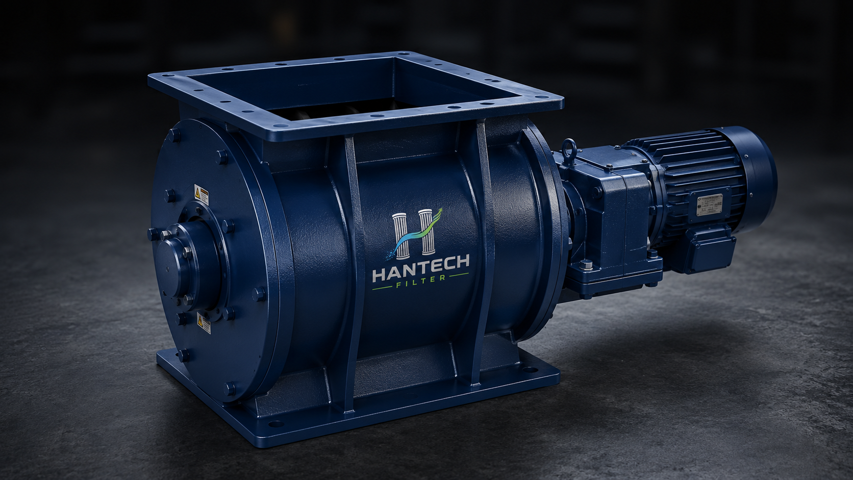
Rotary valve capacity is not selected by body diameter alone. Rotor pocket volume, speed, fill factor, bulk density, differential pressure and air leakage must be evaluated together.
Data to Check First When Selecting a Rotary Valve
Selecting a rotary valve (airlock) requires the target throughput, material bulk density and flow behaviour, net pocket volume per revolution, operating speed, actual fill factor, differential pressure, temperature and wear conditions. Two valves with the same nominal body size will not deliver the same capacity or sealing performance if their rotor geometry, tip clearance, inlet and speed differ.
A rotary valve beneath a baghouse hopper has two duties: discharge collected dust continuously and limit uncontrolled air entering the filter. When it feeds a pneumatic conveying line, consistent metering and control of leakage across the pressure differential are added. A catalog t/h value is therefore not a final selection until application data are verified.
How Is Rotary Valve Capacity Calculated?
An initial volumetric capacity check can be made with Qv = Vrev × n × 60 × ηf. Here Qv is volumetric capacity in m³/h, Vrev is theoretical pocket volume per revolution (m³/rev), n is rotor speed (rpm), and ηf is the actual fill factor between 0 and 1. For mass capacity, use Qm = Qv × ρb, where ρb is the material's loose bulk density.
Worked capacity example
- Net volume per revolution Vrev
- 0.010 m³/rev
- Rotor speed n
- 12 rpm
- Example fill factor ηf
- 0.65 (example)
- Bulk density ρb
- 850 kg/m³
- Volumetric capacity
- 0.010 × 12 × 60 × 0.65 = 4.68 m³/h
- Mass capacity
- 4.68 × 850 = 3,978 kg/h ≈ 4.0 t/h
The 0.65 fill factor in this example only demonstrates the method. Actual filling varies with material flowability, rotor speed, inlet geometry, pocket aeration, adhesion and differential pressure. Vrev must come from the rotor's net usable volume or the manufacturer's drawing, not the nominal housing volume.
Why Must Speed and Fill Factor Be Evaluated Together?
| Variable | Effect on capacity | Limit / risk |
|---|---|---|
| Rotor speed | In theory, conveyed volume rises with speed. | If pockets do not have time to fill, actual fill can fall while wear and shearing risk rise. |
| Fill factor | Converts theoretical pocket volume to actual feed. | It must not be treated as constant for sticky, aerated or bridging materials. |
| Bulk density | Determines the kg/h result for the same m³/h. | Use a representative loose bulk density at the valve inlet, not compacted density. |
| Inlet | Affects how the pockets are filled. | A restricted throat or poor hopper flow limits capacity even with a large valve. |
| Differential pressure | Affects gas leakage and pocket discharge. | Higher differential pressure can change capacity, wear and pneumatic-line balance. |
How Does Air Leakage Affect Capacity and the Filter?
Gas passes from the high-pressure side to the low-pressure side through the operating clearances between the rotor tips and housing. This air leakage is not zero; it varies with rotor type, clearance, valve size, speed, temperature, wear and differential pressure. Under a negative-pressure baghouse, air drawn into the filter through the valve can consume usable fan capacity. In a positive-pressure pneumatic line, upward leakage can aerate material in the hopper and reduce pocket filling.
A catalog leakage value is meaningful only at the stated clearance, temperature and differential pressure. Leakage can rise as wear enlarges the clearance, while thermal expansion of the rotor and housing can change seizure risk at high temperature. For final selection, request leakage data from the manufacturer at the expected operating pressure and temperature.
Rotary Valve Selection Matrix by Dust Properties
| Application / material | Primary design check | Assumption to avoid |
|---|---|---|
| Dry, free-flowing dust below a baghouse hopper | Capacity, air sealing, hopper outlet and continuous discharge | Sizing the valve only to average filter dust load and ignoring peak discharge |
| Abrasive mineral dust | Rotor-tip/housing wear, a suitably low speed and replaceable wear parts | Assuming the standard clearance remains unchanged throughout service life |
| Sticky or moist dust | Pocket clean-out, inlet flow, surface finish and, where necessary, a different feeder | Assuming higher speed will solve bridging |
| Coarse product susceptible to shearing | Rotor opening, shearing force, jamming and product breakage | Using a fine-dust valve at the same speed |
| Hot product | Thermal expansion, bearing/seal arrangement, materials and actual temperature | Applying the cold assembly clearance unchanged to hot operation |
| Feeding a pneumatic conveying line | Line pressure, gas leakage, consistent metering and downstream capacity | Using atmospheric hopper-discharge capacity directly |
From Field Symptom to Root Cause: Rotary Valve Diagnosis
| Symptom | Possible root cause | First checks |
|---|---|---|
| Rotor turns but the hopper level rises | Insufficient actual capacity, low fill factor, bridging or a downstream bottleneck | Check hopper flow, current/speed, pocket filling and downstream flow together. |
| Filter ΔP or fan load changes unexpectedly | Air leakage through the rotary valve or a full hopper | Compare valve clearance/wear, hopper level and system airflow. |
| Capacity fluctuates in the pneumatic line | Upward air leakage, irregular filling or line-pressure variation | Record the differential-pressure trend, rotor speed and continuity of material feed. |
| Current rises and knocking or metallic noise appears | Foreign object, thermal seizure, bearing/shaft fault or coarse-particle shearing | Isolate the equipment under the safe shutdown procedure and perform a mechanical inspection. |
| Capacity declines over time | Material sticking in pockets, inlet buildup, wear or loss of speed | Clean the valve, measure the rotor and housing, and verify the gearbox and speed. |
When I Would Not Select a Standard Rotary Valve
Motor, Gearbox and Automation Checks
Motor and gearbox selection must not be based on average capacity alone. Starting under load, full pockets, jams, product shearing and start-stop frequency all change the torque requirement. Capacity cannot be inferred directly from motor kW; reduction ratio, output speed, service factor and the manufacturer's torque curve must be evaluated together.
Sequence logic also matters in a baghouse application. The rotary valve is generally started before dust arrives and runs for a defined delay after the fan or cleaning system stops to clear material remaining in the hopper. A zero-speed switch, motor-current monitoring or torque protection can identify a stopped rotor before the rest of the system continues running. The final interlock sequence must follow the process safety assessment and control philosophy.
Technical Data Required for a Quote
For a rotary valve quote, provide normal and peak capacity (kg/h or m³/h), material and bulk density, particle size, moisture/stickiness, abrasiveness, product temperature, upstream and downstream pressure, acceptable air leakage, inlet/outlet flange, hopper geometry, operating hours and electrical/automation data. For pneumatic conveying, also provide line pressure, gas flow and downstream equipment.
For product details, see the rotary airlock / rotary valve page; for the hopper and silo side, see the silo equipment selection guide; and for a downstream alternative, see the screw conveyor page. Send process data through the Hantech technical quote form.
Technical Review Note
Technical review: Doğuhan Kırmacı — rotary valve capacity, hopper discharge and air-leakage limits. The example is educational; final capacity and clearance selection must be verified against the manufacturer's drawing, material test and actual process conditions.
Frequently Asked Questions
How is rotary valve capacity calculated?
The initial volumetric check is Qv = Vrev × n × 60 × fill factor. Multiply the result by the material's loose bulk density to obtain mass capacity.
Does rotary valve capacity always rise with speed?
No. Higher speed can reduce pocket filling time, lower the actual fill factor and increase wear or product shearing.
Does a rotary airlock leak air?
Yes. Gas passes through the operating clearances between the rotor and housing. The amount depends on clearance, size, speed, temperature, wear and differential pressure.
Are a cellular wheel and a rotary valve the same equipment?
In practice, the terms usually describe the same equipment family. Feeder and airlock duties can, however, require different performance criteria.
Does a rotary valve provide explosion isolation with combustible dust?
A standard rotary valve cannot be assumed to provide explosion isolation. Product certification, clearance geometry and overall system process safety must be verified separately.